Welcome to AltairKit.com! Home of the New Altair 8800 Kit! |
| Comparing the
Authentic Altair 8800 to the Reproduction Please contact me with ANY questions or comments you have after reading this. Thanks! 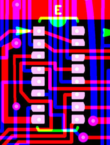 Care was taken
throughout the process of developing the kit to preserve the experience
of building the kit in 1975. For example, no ICs were substituted
for easier to find equivalents. There were some changes made
to the kit for quality and safety purposes. I will explain
for each part of the kit what was changed and the reasons for each
change.
One thing that was changed throughout the kit was the substitution of all disc capacitors with axial capacitors. This was done because those capacitors are easy to damage and don't last as long. All of the PCBs in the kit except for the motherboard have a custom solder mask created by me. This solder mask improves the visual appearance of the boards and helps to make them noticeably different from a real MITS board. It also makes the boards easier to assemble because it helps to prevent bridging a solder joint to a neighboring trace. I created the solder mask by duplicating the copper layer file and deleting all elements except for the pads that required soldering. Special areas like card edge connector and heat sink surface were not covered in mask because that would interfere with proper operation of the board! (Not so much with the heat sink, but it helps!) The sample picture is from the CAD file for the CPU board. You may look at some of the IC pads and wonder why they look so strange, almost like someone cut them in half! Take the picture to the right for an example. The red lines represent traces on the top of the PCB, and the blue traces on the bottom. You can see how a trace passing between a pad on the top also causes a pad on the bottom to get clipped. When a trace passes close to the pads, they get squared off. Unlike most modern PCBs a square pad on these MITS boards does not indicate that the pad is for pin number one. This is how the real MITS boards looked and the style was preserved on the reproduction PCBs.. I will now cover each part of the kit in detail focusing on the PCB artwork, power supply, and case. Quick Anchor Links:
1. Motherboard 2. 8800 1K Static Memory Board 3. 8800 CPU Board 4. 8800 Display / Control Board 5. Power Supply 6. Optima Case 1. Motherboard
 The motherboard was copied from an original MITS 88-EC Revision 0. Erik Klein was very helpful in providing it! Nothing was changed on this board except for ONE thing. The Revision 0 motherboard from MITS was .062 inches thick. Starting with Revision 1 MITS made the motherboards .125 inches thick because people found the .062 boards to be too flimsy. I wanted to provide the earliest experience in building an Altair as well as match the revision of the other PCBs in the kit, so I used the Revision 0 board but changed it to be .125 inch thick. The original MITS kit also included card guides. I have not been able to get new card guides manufactured yet, so they have been left out of the kit. The slots alone hold the boards pretty well, and this is even stated in MITS documentation. They were considered optional. The holes for these card guides are present and in the future hopefully I will have them available. A real MITS card guide can be installed with no problem. 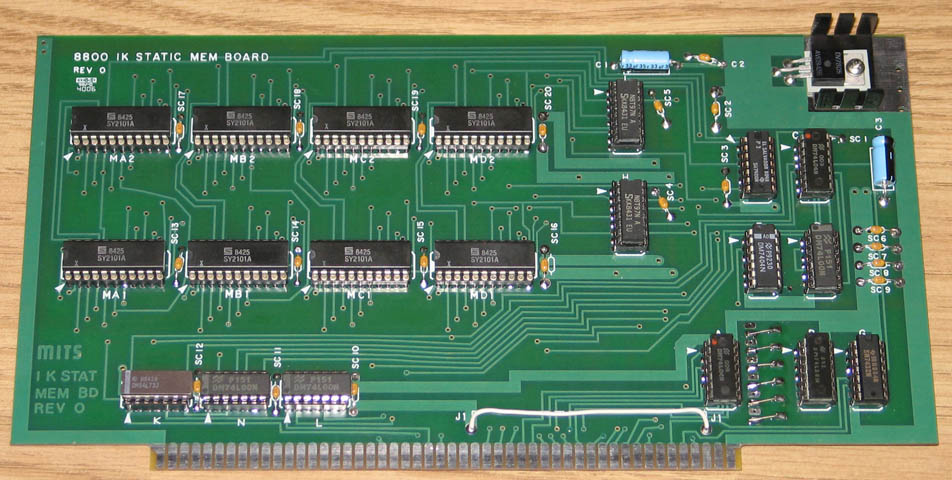 1K memory card kit completed There were no changes to the copper artwork
or component values with the 1k memory card.
MITS used both 8101 and 2101 memory ICs in their kits, and I
have included 2101. I did modify
the silkscreen quite a bit to reflect my interpretation of MITS's intent.
I'm not sure why the silkscreen elements were placed in what
I would consider "the wrong" places and would love to hear any ideas
for it. On this board and the other boards below I have preserved the MITS font,
moved
the silkscreen elements away from soldering areas, and shrunk silkscreen
graphics to fit within the pads. The silkscreen
modifications, in my opinion, make the boards easier to assemble and also look
better. Below are pictures at 1:1 scale showing
some of the differences.
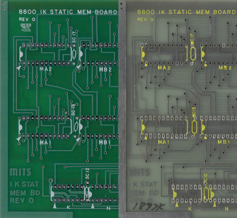 Reproduction on Left, MITS on Right Notice the SC is hard to see on some. The pin 1 arrow doesn't point to pin 1. 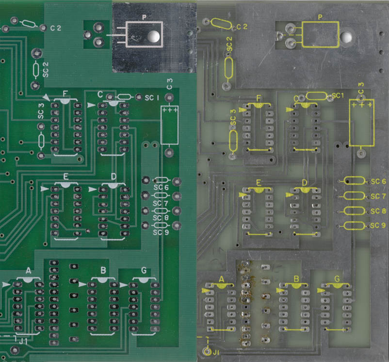 Reproduction on Left, MITS on Right Notice the graphics have been shrunk to fit. 3. 8800 CPU Board 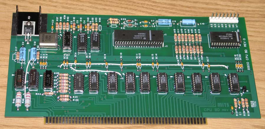 CPU Kit assembled There were only minor changes to the copper artwork but no changes to component values. MITS used an incorrect pin pitch spacing of .150" for the header connector. It should have been .156". This was so close that the connector could be forced into the holes, or as MITS suggested the connector could be cut in half, trimmed, and then soldered as two pieces. The Revision 1 CPU board fixed this with a correct pin pitch. I decided that for quality I would change the pin pitch to .156, yet leave the "Revision 0" markings. I'm not sure what, if any, differences there were between the Revision 1 and Revision 0 MITS CPU boards aside from that connector pitch. There very well may be none.. I also modified silkscreen quite a bit to reflect my interpretation of MITS's intent like with the 1k memory card above. I have preserved the MITS font, moved silkscreen elements away from soldering areas, and shrunk silkscreen graphics to fit within the pads. The silkscreen modifications, in my opinion, make the boards easier to assemble and also look better. Below are pictures at 1:1 scale showing some of the differences. 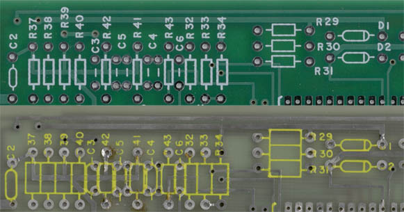 Reproduction on Top, MITS on Bottom Its a good thing that people were provided a printout of the silkscreen in 1975. : ) 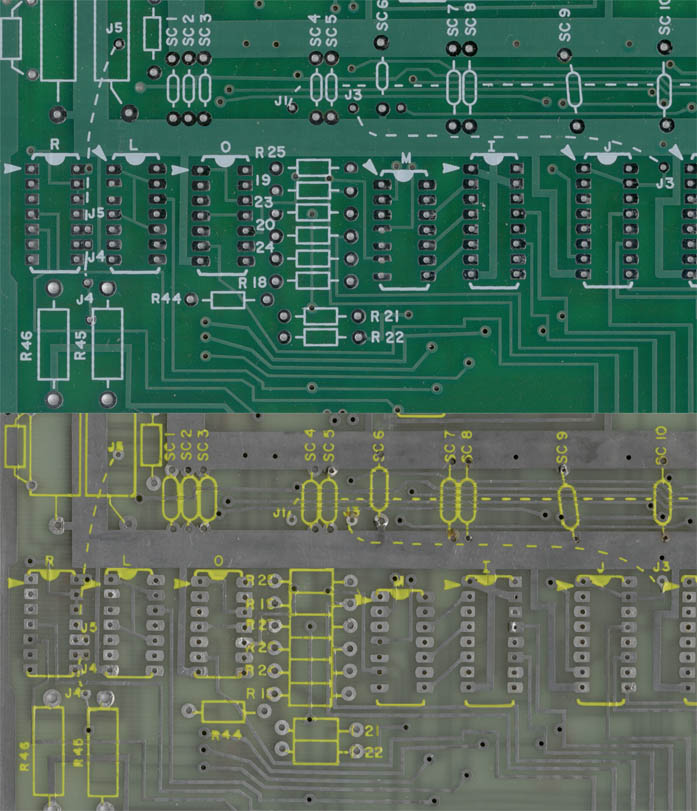 Reproduction on Top, MITS on Bottom Notice the jumpers and their labels. Also the difference in ICs and component graphics. 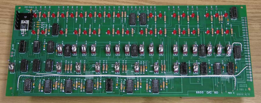 Partially completed display/control board (LEDs have not been soldered) There no changes to the copper artwork or to component values. The silkscreen text objects on my revision 0 board were so bad that I did not feel it could be salvaged. It was hard for me to finally make the decision to replace all of the text objects with a new font. I matched the font as close as I could and then recreated every single letter/number used on the board (except for the copper text in the bottom right corner). There were some minor differences in the font. The biggest differences were "3" had a flat top and now doesn't, "0" (zero) had a slash through it and now doesn't, and "8" was slightly fatter. I was glad that this was the only board I had to change like this. Since this board will only be seen during construction it isn't too bad. Obviously I changed the positioning of the new text to reflect my interpretation of MITS's intent. I have preserved the MITS silkscreen graphics, moved elements away from soldering areas, and shrunk the graphics to fit within the pads. The silkscreen modifications, in my opinion, make the boards easier to assemble and also look better. Below are pictures at 1:1 scale showing some of the differences. 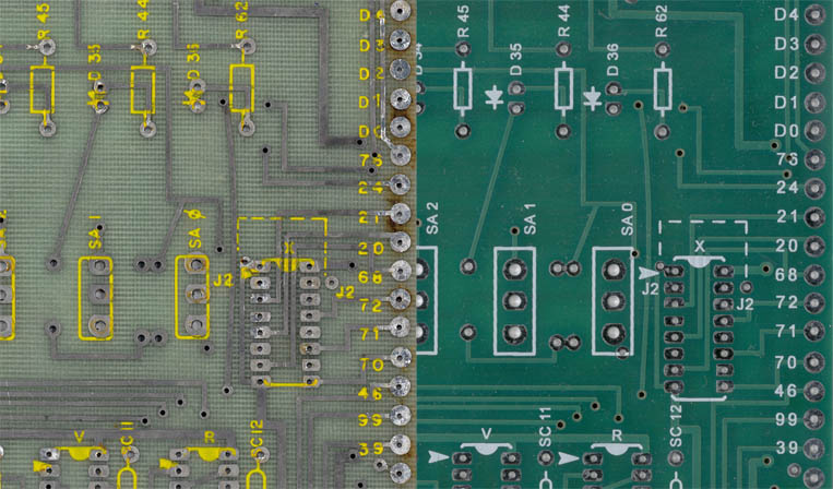 MITS on Left, Reproduction on Right Notice how the S is cut off on SC11 and 12. The diode symbol is also on top of the pads. 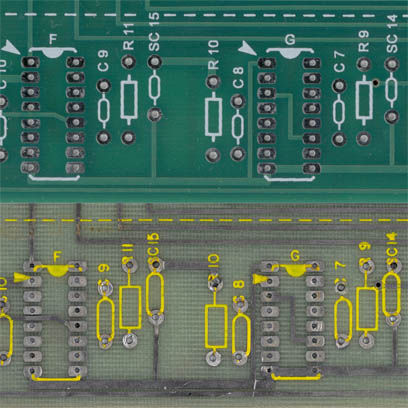 Reproduction on Top, MITS on Bottom The whole bottom row of parts showed this type of congestion. Often the only way of telling a resistor from a capacitor was the symbol! 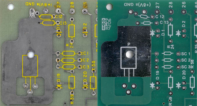 MITS on Left, Reproduction on Right 5. Power Supply 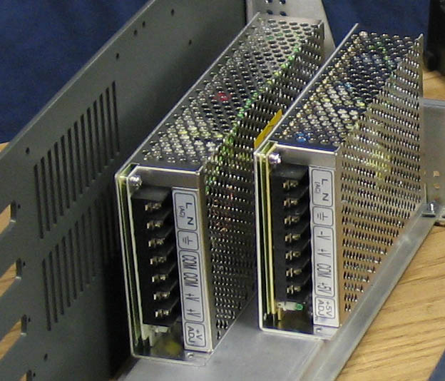 Power Supplies for
the reproduction Altair 8800 Computer Kit
The power supplies used with the reproduction Altair kit are obviously
quite different from the steel boat anchor used with the
original!
Switching power supply technology has many benefits over the
linear transformer power supplies. Noise, efficiency, weight,
size, voltage input options, and safety are a few of the
benefits!
During the debugging of my prototype I accidentally shorted
the
+8v to both +16v and -16v. Instead of making fire, the power
supplies gracefully shut down!The power supplies are internally fused, and have output over voltage protection and output over current protection (overload) circuits. They also automatically recover from these faults when the fault is removed. They are also safer because they do not require the "Power Supply" board which had exposed points of AC voltage right below the connector knockouts. 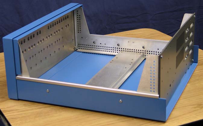 Optima Enclosure The genuine Optima enclosure used in the reproduction is mechanically identical to the vintage Optima enclosure used by MITS. The case has not been manufactured for 20 years and the drawings had been lost. Every detail about the original case was carefully copied, down to the countless holes on the side supports! The front bezel and side trim were made from Aluminum extrusion. Employees who manufactured these cases still work for Optima and remembered a lot of the details about the case and its construction. The case is made by hand with the assistance of CNC (computer numeric control) machinery. The paint/color codes used on the cases is identical to the cases sold in 1975. The front panels are powder coated and then silk screened with white ink. So what are we left with? Hopefully you will agree with me that it is be best combination of modern compromise and historic authenticity! Please contact me with ANY questions or comments you have after reading this. Thanks! Visit Stockly Electronics
Forums for more pictures as they become
available!
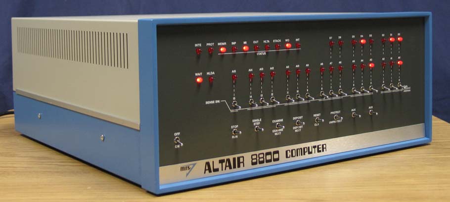 The completed reproduction Altair 8800 Kit Computer. Visit Stockly Electronics Forums for more pictures as they become available! |
| ©2007 Grant Stockly
|